Select a category, then open the product you need. Each table belongs to HIWIN.
Product specifications
Open one family at a time.
No matching model. Try the base code without spaces or suffixes, or send a photo to our team.
Linear motion10 families
HIWIN
Help me choose a HIWIN guideway
Compare the purpose of the eleven guideway series before choosing a block.11 models / configurationsView specs +
Eleven linear guideway series
HIWIN lists these series on its product page. The published load ranges are family-level figures, not a substitute for the block-specific dimensions below.
HIWIN guideway series and published dynamic-load ranges
Series
Format
Published load range
HG
Heavy-duty ball guide
11.38–208.36 kN
EG
Low-profile ball guide
5.35–33.35 kN
CG
High-moment ball guide
See exact block
RG
Roller guide
11.3–275.3 kN
WE
Wide-rail guide
5.23–29.8 kN
MG
Miniature MGN / MGW
0.68–8.93 kN
QH
SynchMotion HG-type
13.88–108.72 kN
QE
SynchMotion EG-type
8.56–51.18 kN
QW
SynchMotion wide-rail
16–36.8 kN
QR
SynchMotion roller guide
26.3–150.8 kN
PG
Guideway with encoder
See exact system
HIWIN
Heavy-duty square guides
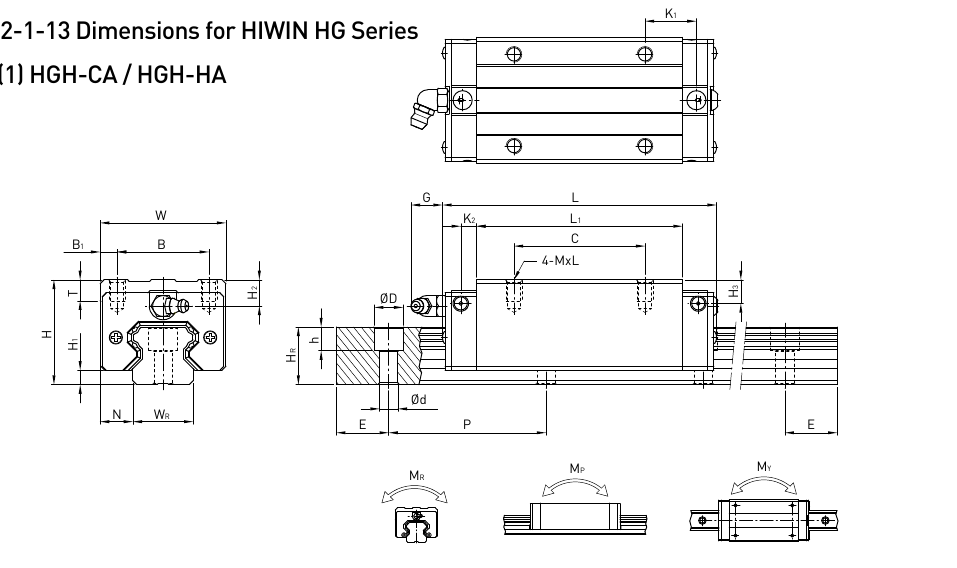
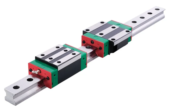
HGH · Standard CA and long HA blocks for machine axes.15 models / configurationsView specs +
HGH square guide blocks
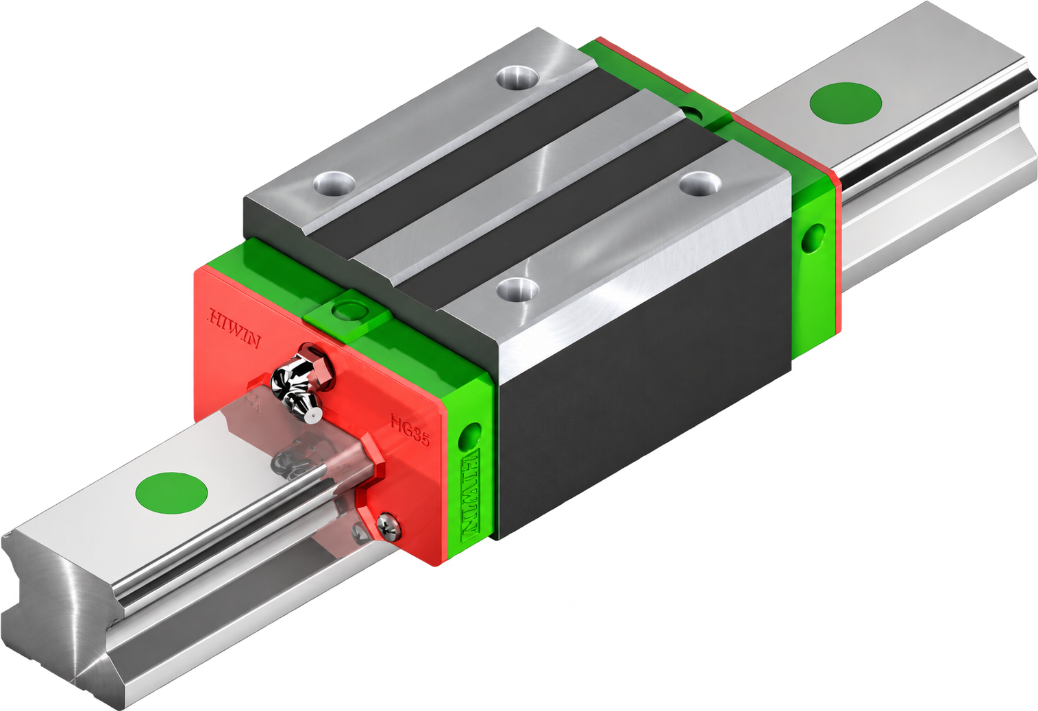
Standard CA and long HA blocks for heavy-duty linear motion.
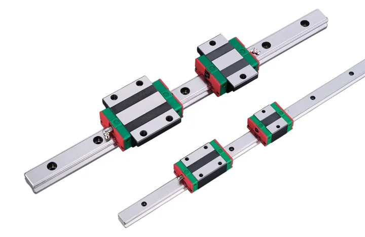
HIWIN carriage and rail product view.Mounting and rail drawing · open to enlarge
HGH square guide blocks · mounting, rail, load and weight data
Model
Assembly H (mm)
H₁ (mm)
N (mm)
Block W (mm)
B (mm)
B₁ (mm)
Mounting C (mm)
L₁ (mm)
Block L (mm)
K₁ (mm)
K₂ (mm)
G (mm)
Block thread M×l
T (mm)
H₂ (mm)
H₃ (mm)
Rail Wᵣ (mm)
Rail Hᵣ (mm)
Rail hole D (mm)
Rail hole h (mm)
Rail hole d (mm)
Rail pitch P (mm)
Rail end E (mm)
Rail bolt
Dynamic C (kN)
Static C₀ (kN)
Mᵣ (kN·m)
Mₚ (kN·m)
Mᵧ (kN·m)
Block (kg)
Rail (kg/m)
HGH15CA
28
4.3
9.5
34
26
4
26
39.4
61.4
10
4.85
5.3
M4x5
6
7.95
7.7
15
15
7.5
5.3
4.5
60
20
M4x16
14.7
23.47
0.12
0.14
0.14
0.18
1.45
HGH20CA
30
4.6
12
44
32
6
36
50.5
77.5
12.25
6
12
M5x6
8
6
6
20
17.5
9.5
8.5
6
60
20
M5x16
27.1
36.68
0.27
0.28
0.28
0.30
2.21
HGH20HA
30
4.6
12
44
32
6
50
65.2
92.2
12.6
6
12
M5x6
8
6
6
20
17.5
9.5
8.5
6
60
20
M5x16
32.7
47.96
0.35
0.48
0.48
0.39
2.21
HGH25CA
40
5.5
12.5
48
35
6.5
35
58
84
15.7
6
12
M6x8
8
10
9
23
22
11
9
7
60
20
M6x20
34.9
52.82
0.42
0.49
0.49
0.51
3.21
HGH25HA
40
5.5
12.5
48
35
6.5
50
78.6
104.6
18.5
6
12
M6x8
8
10
9
23
22
11
9
7
60
20
M6x20
42.2
69.07
0.56
0.73
0.73
0.69
3.21
HGH30CA
45
6
16
60
40
10
40
70
97.4
20.25
6
12
M8x10
8.5
9.5
13.8
28
26
14
12
9
80
20
M8x25
48.5
71.87
0.66
0.7
0.7
0.88
4.47
HGH30HA
45
6
16
60
40
10
60
93
120.4
21.75
6
12
M8x10
8.5
9.5
13.8
28
26
14
12
9
80
20
M8x25
58.6
93.99
0.88
1.23
1.23
1.16
4.47
HGH35CA
55
7.5
18
70
50
10
50
80
112.4
20.6
7
12
M8x12
10.2
16
19.6
34
29
14
12
9
80
20
M8x25
64.6
93.88
1.16
1.09
1.09
1.45
6.30
HGH35HA
55
7.5
18
70
50
10
72
105.8
138.2
22.5
7
12
M8x12
10.2
16
19.6
34
29
14
12
9
80
20
M8x25
77.9
122.77
1.54
2.02
2.02
1.92
6.30
HGH45CA
70
9.5
20.5
86
60
13
60
97
139.4
23
10
12.9
M10x17
16
18.5
30.5
45
38
20
17
14
105
22.5
M12x35
103.8
146.71
1.98
2.35
2.35
2.73
10.41
HGH45HA
70
9.5
20.5
86
60
13
80
128.8
171.2
28.9
10
12.9
M10x17
16
18.5
30.5
45
38
20
17
14
105
22.5
M12x35
125.3
191.85
2.63
4.45
4.45
3.61
10.41
HGH55CA
80
13
23.5
100
75
12.5
75
117.7
166.7
27.35
11
12.9
M12x18
17.5
22
29
53
44
23
20
16
120
30
M14x45
153.2
211.23
3.69
3.684
3.684
4.17
15.08
HGH55HA
80
13
23.5
100
75
12.5
95
155.8
204.8
36.4
11
12.9
M12x18
17.5
22
29
53
44
23
20
16
120
30
M14x45
184.9
276.23
4.88
6.65
6.65
5.49
15.08
HGH65CA
90
15
31.5
126
76
25
70
144.2
200.2
43.1
14
12.9
M16x20
25
15
15
63
53
26
22
18
150
35
M16x50
213.2
287.48
6.65
5.87
5.87
7.00
21.18
HGH65HA
90
15
31.5
126
76
25
120
203.6
259.6
47.8
14
12.9
M16x20
25
15
15
63
53
26
22
18
150
35
M16x50
277.8
420.17
9.38
12.574
12.574
9.82
21.18
H = assembled height · W/L = block width/length · Wᵣ = rail width · P = rail-hole pitch. Dynamic and static ratings are in kN; rated moments are in kN·m. Block and rail weights are in kg and kg/m.
HIWIN
Heavy-duty flanged guides
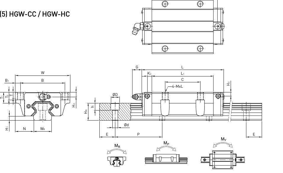
HGW · A wider flange for mounting the carriage.15 models / configurationsView specs +
HGW flanged guide blocks
Wide mounting flange, with standard CC and long HC block formats.
HGW flanged guide blocks · mounting, rail, load and weight data
Model
Assembly H (mm)
H₁ (mm)
N (mm)
Block W (mm)
B (mm)
B₁ (mm)
Mounting C (mm)
L₁ (mm)
Block L (mm)
K₁ (mm)
K₂ (mm)
G (mm)
Block thread M
T (mm)
T₁ (mm)
T₂ (mm)
H₂ (mm)
H₃ (mm)
Rail Wᵣ (mm)
Rail Hᵣ (mm)
Rail hole D (mm)
Rail hole h (mm)
Rail hole d (mm)
Rail pitch P (mm)
Rail end E (mm)
Rail bolt
Dynamic C (kN)
Static C₀ (kN)
Mᵣ (kN·m)
Mₚ (kN·m)
Mᵧ (kN·m)
Block (kg)
Rail (kg/m)
HGW15CC
24
4.3
16
47
38
4.5
30
39.4
61.4
8
4.85
5.3
M5
6
8.9
6.95
3.95
3.7
15
15
7.5
5.3
4.5
60
20
M4x16
14.7
23.47
0.12
0.14
0.14
0.17
1.45
HGW20CC
30
4.6
21.5
63
53
5
40
50.5
77.5
10.25
6
12
M6
8
10
9.5
6
6
20
17.5
9.5
8.5
6
60
20
M5x16
27.1
36.68
0.27
0.28
0.28
0.40
2.21
HGW20HC
30
4.6
21.5
63
53
5
40
65.2
92.2
17.6
6
12
M6
8
10
9.5
6
6
20
17.5
9.5
8.5
6
60
20
M5x16
32.7
47.96
0.35
0.48
0.48
0.52
2.21
HGW25CC
36
5.5
23.5
70
57
6.5
45
58
84
10.7
6
12
M8
8
14
10
6
5
23
22
11
9
7
60
20
M6x20
34.9
52.82
0.42
0.49
0.49
0.59
3.21
HGW25HC
36
5.5
23.5
70
57
6.5
45
78.6
104.6
21
6
12
M8
8
14
10
6
5
23
22
11
9
7
60
20
M6x20
42.2
69.07
0.56
0.73
0.73
0.80
3.21
HGW30CC
42
6
31
90
72
9
52
70
97.4
14.25
6
12
M10
8.5
16
10
6.5
10.8
28
26
14
12
9
80
20
M8x25
48.5
71.87
0.66
0.7
0.7
1.09
4.47
HGW30HC
42
6
31
90
72
9
52
93
120.4
25.75
6
12
M10
8.5
16
10
6.5
10.8
28
26
14
12
9
80
20
M8x25
58.6
93.99
0.88
1.23
1.23
1.44
4.47
HGW35CC
48
7.5
33
100
82
9
62
80
112.4
14.6
7
12
M10
10.1
18
13
9
12.6
34
29
14
12
9
80
20
M8x25
64.6
93.88
1.16
1.09
1.09
1.56
6.30
HGW35HC
48
7.5
33
100
82
9
62
105.8
138.2
27.5
7
12
M10
10.1
18
13
9
12.6
34
29
14
12
9
80
20
M8x25
77.9
122.77
1.54
2.02
2.02
2.06
6.30
HGW45CC
60
9.5
37.5
120
100
10
80
97
139.4
13
10
12.9
M12
15.1
22
15
8.5
20.5
45
38
20
17
14
105
22.5
M12x35
103.8
146.71
1.98
2.35
2.35
2.79
10.41
HGW45HC
60
9.5
37.5
120
100
10
80
128.8
171.2
28.9
10
12.9
M12
15.1
22
15
8.5
20.5
45
38
20
17
14
105
22.5
M12x35
125.3
191.85
2.63
4.45
4.45
3.69
10.41
HGW55CC
70
13
43.5
140
116
12
95
117.7
166.7
17.35
11
12.9
M14
17.5
26.5
17
12
19
53
44
23
20
16
120
30
M14x45
153.2
211.23
3.69
3.684
3.684
4.52
15.08
HGW55HC
70
13
43.5
140
116
12
95
155.8
204.8
36.4
11
12.9
M14
17.5
26.5
17
12
19
53
44
23
20
16
120
30
M14x45
184.9
276.23
4.88
6.65
6.65
5.96
15.08
HGW65CC
90
15
53.5
170
142
14
110
144.2
200.2
23.1
14
12.9
M16
25
37.5
23
15
15
63
53
26
22
18
150
35
M16x50
213.2
287.48
6.65
5.87
5.87
9.17
21.18
HGW65HC
90
15
53.5
170
142
14
110
203.6
259.6
52.8
14
12.9
M16
25
37.5
23
15
15
63
53
26
22
18
150
35
M16x50
277.8
420.17
9.38
12.574
12.574
12.89
21.18
H = assembled height · W/L = block width/length · Wᵣ = rail width · P = rail-hole pitch. Dynamic and static ratings are in kN; rated moments are in kN·m. Block and rail weights are in kg and kg/m.
HIWIN
Low-height heavy-duty guides
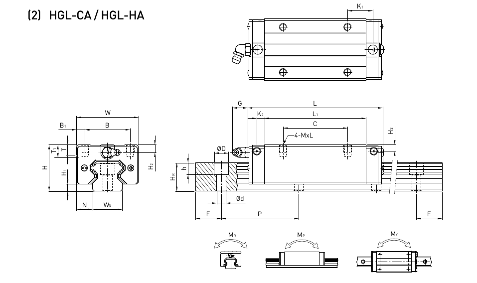
HGL · A lower assembly in the HG family.11 models / configurationsView specs +
HGL low-height guide blocks
Lower assembly height in the HG family; standard CA and long HA blocks.
HGL low-height guide blocks · mounting, rail, load and weight data
Model
Assembly H (mm)
H₁ (mm)
N (mm)
Block W (mm)
B (mm)
B₁ (mm)
Mounting C (mm)
L₁ (mm)
Block L (mm)
K₁ (mm)
K₂ (mm)
G (mm)
Block thread M×l
T (mm)
H₂ (mm)
H₃ (mm)
Rail Wᵣ (mm)
Rail Hᵣ (mm)
Rail hole D (mm)
Rail hole h (mm)
Rail hole d (mm)
Rail pitch P (mm)
Rail end E (mm)
Rail bolt
Dynamic C (kN)
Static C₀ (kN)
Mᵣ (kN·m)
Mₚ (kN·m)
Mᵧ (kN·m)
Block (kg)
Rail (kg/m)
HGL15CA
24
4.3
9.5
34
26
4
26
39.4
61.4
10
4.85
5.3
M4x4
6
3.95
3.7
15
15
7.5
5.3
4.5
60
20
M4x16
14.7
23.47
0.12
0.14
0.14
0.14
1.45
HGL25CA
36
5.5
12.5
48
35
6.5
35
58
84
15.7
6
12
M6x6
8
6
5
23
22
11
9
7
60
20
M6x20
34.9
52.82
0.42
0.49
0.49
0.42
3.21
HGL25HA
36
5.5
12.5
48
35
6.5
50
78.6
104.6
18.5
6
12
M6x6
8
6
5
23
22
11
9
7
60
20
M6x20
42.2
69.07
0.56
0.73
0.73
0.57
3.21
HGL30CA
42
6
16
60
40
10
40
70
97.4
20.25
6
12
M8x10
8.5
6.5
10.8
28
26
14
12
9
80
20
M8x25
48.5
71.87
0.66
0.7
0.7
0.78
4.47
HGL30HA
42
6
16
60
40
10
60
93
120.4
21.75
6
12
M8x10
8.5
6.5
10.8
28
26
14
12
9
80
20
M8x25
58.6
93.99
0.88
1.23
1.23
1.03
4.47
HGL35CA
48
7.5
18
70
50
10
50
80
112.4
20.6
7
12
M8x12
10.2
9
12.6
34
29
14
12
9
80
20
M8x25
64.6
93.88
1.16
1.09
1.09
1.14
6.30
HGL35HA
48
7.5
18
70
50
10
72
105.8
138.2
22.5
7
12
M8x12
10.2
9
12.6
34
29
14
12
9
80
20
M8x25
77.9
122.77
1.54
2.02
2.02
1.52
6.30
HGL45CA
60
9.5
20.5
86
60
13
60
97
139.4
23
10
12.9
M10x17
16
8.5
20.5
45
38
20
17
14
105
22.5
M12x35
103.8
146.71
1.98
2.35
2.35
2.08
10.41
HGL45HA
60
9.5
20.5
86
60
13
80
128.8
171.2
28.9
10
12.9
M10x17
16
8.5
20.5
45
38
20
17
14
105
22.5
M12x35
125.3
191.85
2.63
4.45
4.45
2.75
10.41
HGL55CA
70
13
23.5
100
75
12.5
75
117.7
166.7
27.35
11
12.9
M12x18
17.5
12
19
53
44
23
20
16
120
30
M14x45
153.2
211.23
3.69
3.684
3.684
3.25
15.08
HGL55HA
70
13
23.5
100
75
12.5
95
155.8
204.8
36.4
11
12.9
M12x18
17.5
12
19
53
44
23
20
16
120
30
M14x45
184.9
276.23
4.88
6.65
6.65
4.27
15.08
H = assembled height · W/L = block width/length · Wᵣ = rail width · P = rail-hole pitch. Dynamic and static ratings are in kN; rated moments are in kN·m. Block and rail weights are in kg and kg/m.
HIWIN
Low-profile square guides
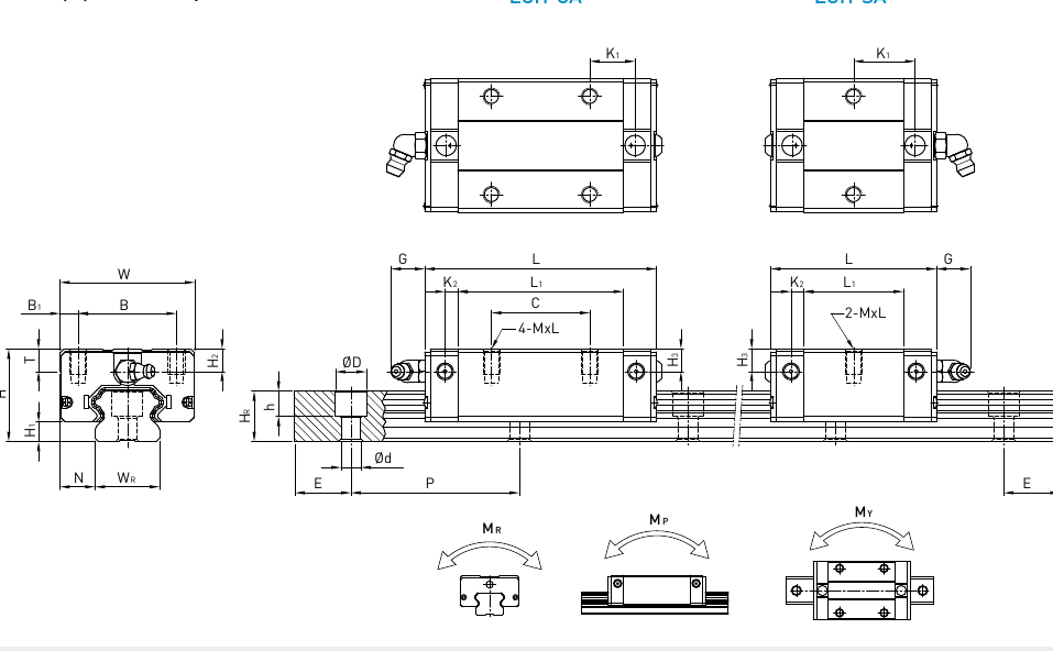
EGH · Short SA and standard CA blocks where height is limited.10 models / configurationsView specs +
EGH low-profile square blocks
Short SA and standard CA blocks for machines with limited installation height.
EGH low-profile square blocks · mounting, rail, load and weight data
Model
Assembly H (mm)
H₁ (mm)
N (mm)
Block W (mm)
B (mm)
B₁ (mm)
Mounting C (mm)
L₁ (mm)
Block L (mm)
K₁ (mm)
K₂ (mm)
G (mm)
Block thread M×l
T (mm)
H₂ (mm)
H₃ (mm)
Rail Wᵣ (mm)
Rail Hᵣ (mm)
Rail hole D (mm)
Rail hole h (mm)
Rail hole d (mm)
Rail pitch P (mm)
Rail end E (mm)
Rail bolt
Dynamic C (kN)
Static C₀ (kN)
Mᵣ (kN·m)
Mₚ (kN·m)
Mᵧ (kN·m)
Block (kg)
Rail (kg/m)
EGH15SA
24
4.5
9.5
34
26
4
-
23.1
40.1
14.8
3.5
5.7
M4x6
6
5.5
6
15
12.5
6
4.5
3.5
60
20
M3x16
5.35
9.40
0.08
0.04
0.04
0.09
1.25
EGH15CA
24
4.5
9.5
34
26
4
26
39.8
56.8
10.15
3.5
5.7
M4x6
6
5.5
6
15
12.5
6
4.5
3.5
60
20
M3x16
7.83
16.19
0.13
0.10
0.10
0.15
1.25
EGH20SA
28
6
11
42
32
5
-
29
50
18.75
4.15
12
M5x7
7.5
6
6
20
15.5
9.5
8.5
6
60
20
M5x16
7.23
12.74
0.13
0.06
0.06
0.15
2.08
EGH20CA
28
6
11
42
32
5
32
48.1
69.1
12.3
4.15
12
M5x7
7.5
6
6
20
15.5
9.5
8.5
6
60
20
M5x16
10.31
21.13
0.22
0.16
0.16
0.24
2.08
EGH25SA
33
7
12.5
48
35
6.5
-
35.5
59.1
21.9
4.55
12
M6x9
8
8
8
23
18
11
9
7
60
20
M6x20
11.40
19.50
0.23
0.12
0.12
0.25
2.67
EGH25CA
33
7
12.5
48
35
6.5
35
59
82.6
16.15
4.55
12
M6x9
8
8
8
23
18
11
9
7
60
20
M6x20
16.27
32.40
0.38
0.32
0.32
0.41
2.67
EGH30SA
42
10
16
60
40
10
-
41.5
69.5
26.75
6
12
M8x12
9
8
9
28
23
11
9
7
80
20
M6x25
16.42
28.10
0.40
0.21
0.21
0.45
4.35
EGH30CA
42
10
16
60
40
10
40
70.1
98.1
21.05
6
12
M8x12
9
8
9
28
23
11
9
7
80
20
M6x25
23.70
47.46
0.68
0.55
0.55
0.76
4.35
EGH35SA
48
11
18
70
50
10
-
45
75
28.5
7
12
M8x12
10
8.5
8.5
34
27.5
14
12
9
80
20
M8x25
22.66
37.38
0.56
0.31
0.31
0.74
6.14
EGH35CA
48
11
18
70
50
10
50
78
108
20
7
12
M8x12
10
8.5
8.5
34
27.5
14
12
9
80
20
M8x25
33.35
64.84
0.98
0.69
0.69
1.10
6.14
H = assembled height · W/L = block width/length · Wᵣ = rail width · P = rail-hole pitch. Dynamic and static ratings are in kN; rated moments are in kN·m. Block and rail weights are in kg and kg/m.
HIWIN
Low-profile flanged guides
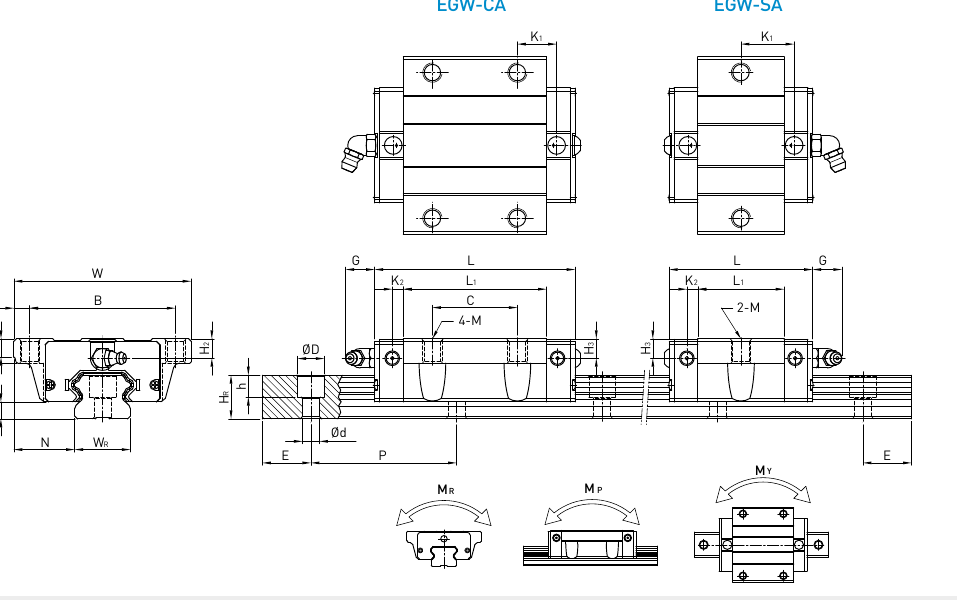
EGW · Low installation height with a wider mounting flange.10 models / configurationsView specs +
EGW low-profile flanged blocks
Flanged mounting in the EG family, with short SA and standard CA formats.
EGW low-profile flanged blocks · mounting, rail, load and weight data
Model
Assembly H (mm)
H₁ (mm)
N (mm)
Block W (mm)
B (mm)
B₁ (mm)
Mounting C (mm)
L₁ (mm)
Block L (mm)
K₁ (mm)
K₂ (mm)
G (mm)
Block thread M
T (mm)
T₁ (mm)
H₂ (mm)
H₃ (mm)
Rail Wᵣ (mm)
Rail Hᵣ (mm)
Rail hole D (mm)
Rail hole h (mm)
Rail hole d (mm)
Rail pitch P (mm)
Rail end E (mm)
Rail bolt
Dynamic C (kN)
Static C₀ (kN)
Mᵣ (kN·m)
Mₚ (kN·m)
Mᵧ (kN·m)
Block (kg)
Rail (kg/m)
EGW15SA
24
4.5
18.5
52
41
5.5
-
23.1
40.1
14.8
3.5
5.7
M5
5
7
5.5
6
15
12.5
6
4.5
3.5
60
20
M3x16
5.35
9.40
0.08
0.04
0.04
0.12
1.25
EGW15CA
24
4.5
18.5
52
41
5.5
26
39.8
56.8
10.15
3.5
5.7
M5
5
7
5.5
6
15
12.5
6
4.5
3.5
60
20
M3x16
7.83
16.19
0.13
0.10
0.10
0.21
1.25
EGW20SA
28
6
19.5
59
49
5
-
29
50
18.75
4.15
12
M6
7
9
6
6
20
15.5
9.5
8.5
6
60
20
M5x16
7.23
12.74
0.13
0.06
0.06
0.19
2.08
EGW20CA
28
6
19.5
59
49
5
32
48.1
69.1
12.3
4.15
12
M6
7
9
6
6
20
15.5
9.5
8.5
6
60
20
M5x16
10.31
21.13
0.22
0.16
0.16
0.32
2.08
EGW25SA
33
7
25
73
60
6.5
-
35.5
59.1
21.9
4.55
12
M8
7.5
10
8
8
23
18
11
9
7
60
20
M6x20
11.40
19.50
0.23
0.12
0.12
0.35
2.67
EGW25CA
33
7
25
73
60
6.5
35
59
82.6
16.15
4.55
12
M8
7.5
10
8
8
23
18
11
9
7
60
20
M6x20
16.27
32.40
0.38
0.32
0.32
0.59
2.67
EGW30SA
42
10
31
90
72
9
-
41.5
69.5
26.75
6
12
M10
7
10
8
9
28
23
11
9
7
80
20
M6x25
16.42
28.10
0.40
0.21
0.21
0.62
4.35
EGW30CA
42
10
31
90
72
9
40
70.1
98.1
21.05
6
12
M10
7
10
8
9
28
23
11
9
7
80
20
M6x25
23.70
47.46
0.68
0.55
0.55
1.04
4.35
EGW35SA
48
11
33
100
82
9
-
45
75
28.5
7
12
M10
10
13
8.5
8.5
34
27.5
14
12
9
80
20
M8x25
22.66
37.38
0.56
0.31
0.31
0.84
6.14
EGW35CA
48
11
33
100
82
9
50
78
108
20
7
12
M10
10
13
8.5
8.5
34
27.5
14
12
9
80
20
M8x25
33.35
64.84
0.98
0.69
0.69
1.45
6.14
H = assembled height · W/L = block width/length · Wᵣ = rail width · P = rail-hole pitch. Dynamic and static ratings are in kN; rated moments are in kN·m. Block and rail weights are in kg and kg/m.
HIWIN
Miniature narrow guides
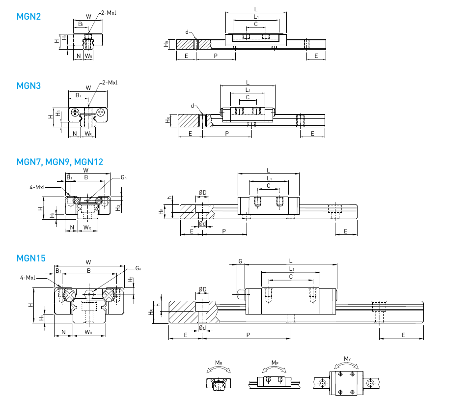
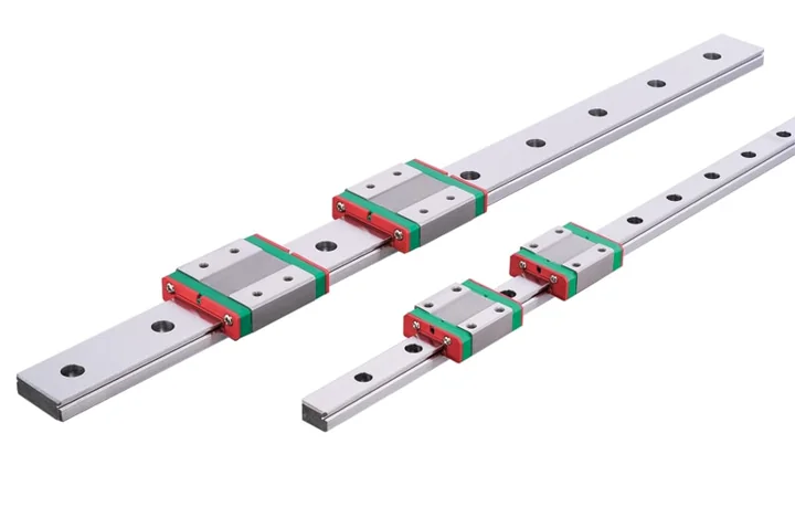
MGN · Compact rails and blocks for small precision mechanisms.11 models / configurationsView specs +
MGN miniature narrow guides
Compact narrow-rail guides in sizes 2, 3, 7, 9, 12 and 15; C and H block lengths.R is rail width. Dimensions in millimetres.
MGN miniature narrow guides · mounting, rail, load and weight data
Model
Assembly H (mm)
H₁ (mm)
N (mm)
Block W (mm)
B (mm)
B₁ (mm)
Mounting C (mm)
L₁ (mm)
Block L (mm)
Maximum L (mm)
G (mm)
Lubrication Gn
Block thread M×l
H₂ (mm)
Rail Wᵣ (mm)
Rail Hᵣ (mm)
Rail hole D (mm)
Rail hole h (mm)
Rail hole d (mm)
Rail pitch P (mm)
Rail end E (mm)
Rail bolt
Dynamic C (kN)
Static C₀ (kN)
Mᵣ (N·m)
Mₚ (N·m)
Mᵧ (N·m)
Block (kg)
Rail (kg/m)
MGN2C
3.2
0.7
2
6
—
3
4
9.4
12.5
12.5
—
—
M1.4 THRU
—
2
2
M1 THRU
—
—
8
4
M1
0.22
0.4
0.42
0.63
0.63
0.001
0.03
MGN3C
4
1
2.5
8
—
4
3.5
7
11.3
11.3
—
—
M1.6×1.3
—
3
2.6
M1.6 THRU
—
—
10
5
M1.6
0.29
0.44
0.7
0.5
0.5
0.001
0.05
MGN3H
4
1
2.5
8
—
4
5.5
11
15.3
15.3
—
—
M2×1.3
—
3
2.6
M1.6 THRU
—
—
10
5
M1.6
0.39
0.68
1.0
1.3
1.3
0.002
0.05
MGN7C
8
1.5
5
17
12
2.5
8
13.5
22.5
23.1
—
Ø1.2
M2×2.5
1.5
7
4.8
4.2
2.3
2.4
15
5
M2×6
0.98
1.24
4.70
2.84
2.84
0.010
0.22
MGN7H
8
1.5
5
17
12
2.5
13
21.8
30.8
31.4
—
Ø1.2
M2×2.5
1.5
7
4.8
4.2
2.3
2.4
15
5
M2×6
1.37
1.96
7.64
4.80
4.80
0.015
0.22
MGN9C
10
2
5.5
20
15
2.5
10
18.9
28.9
29.9
—
Ø1.4
M3×3
1.8
9
6.5
6
3.5
3.5
20
7.5
M3×8
1.86
2.55
11.76
7.35
7.35
0.016
0.38
MGN9H
10
2
5.5
20
15
2.5
16
29.9
39.9
40.9
—
Ø1.4
M3×3
1.8
9
6.5
6
3.5
3.5
20
7.5
M3×8
2.55
4.02
19.60
18.62
18.62
0.026
0.38
MGN12C
13
3
7.5
27
20
3.5
15
21.7
34.7
35.1
—
Ø2
M3×3.5
2.5
12
8
6
4.5
3.5
25
10
M3×8
2.84
3.92
25.48
13.72
13.72
0.034
0.65
MGN12H
13
3
7.5
27
20
3.5
20
32.4
45.4
45.8
—
Ø2
M3×3.5
2.5
12
8
6
4.5
3.5
25
10
M3×8
3.72
5.88
38.22
36.26
36.26
0.054
0.65
MGN15C
16
4
8.5
32
25
3.5
20
26.7
42.1
42.7
4.5
M3
M3×4
3
15
10
6
4.5
3.5
40
15
M3×10
4.61
5.59
45.08
21.56
21.56
0.059
1.06
MGN15H
16
4
8.5
32
25
3.5
25
43.4
58.8
59.4
4.5
M3
M3×4
3
15
10
6
4.5
3.5
40
15
M3×10
6.37
9.11
73.50
57.82
57.82
0.092
1.06
H = assembled height · W/L = block width/length · Wᵣ = rail width · P = rail-hole pitch. Dynamic and static ratings are in kN; rated moments are in N·m. Block and rail weights are in kg and kg/m.
HIWIN
Miniature wide guides
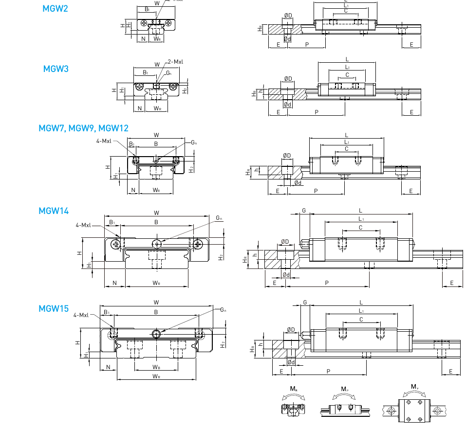
MGW · A wider rail for compact mechanisms.13 models / configurationsView specs +
MGW miniature wide guides
Wider rail and carriage for miniature axes; sizes 2, 3, 7, 9, 12, 14 and 15.
MGW miniature wide guides · mounting, rail, load and weight data
Model
Assembly H (mm)
H₁ (mm)
N (mm)
Block W (mm)
B (mm)
B₁ (mm)
Mounting C (mm)
L₁ (mm)
Block L (mm)
Maximum L (mm)
G (mm)
Lubrication Gn
Block thread M×l
H₂ (mm)
Rail Wᵣ (mm)
Rail Wᵦ (mm)
Rail Hᵣ (mm)
Rail hole D (mm)
Rail hole h (mm)
Rail hole d (mm)
Rail pitch P (mm)
Rail end E (mm)
Rail bolt
Dynamic C (kN)
Static C₀ (kN)
Mᵣ (N·m)
Mₚ (N·m)
Mᵧ (N·m)
Block (kg)
Rail (kg/m)
MGW2C
4
1
3
10
—
5
6.5
11.9
16.7
16.7
—
—
M2×1.3
—
4
—
2.6
2.8
1
1.8
10
5
M1.6
0.41
0.73
1.1
2.2
2.2
0.002
0.07
MGW3C
4.5
1
3
12
—
6
4.5
9.6
15
15.2
—
Ø0.5
M2 THRU
0.65
6
—
2.9
3.6
1.5
2.4
15
5
M2
0.54
0.84
2.3
1.3
1.3
0.003
0.13
MGW3H
4.5
1
3
12
—
6
8
14.2
19.6
19.8
—
Ø0.5
M2 THRU
0.65
6
—
2.9
3.6
1.5
2.4
15
5
M2
0.68
1.18
3.3
2.7
2.7
0.004
0.13
MGW7C
9
1.9
5.5
25
19
3
10
21
31.2
32.2
—
Ø1.2
M3×3
1.85
14
—
5.2
6
3.2
3.5
30
10
M3×6
1.37
2.06
15.70
7.14
7.14
0.020
0.51
MGW7H
9
1.9
5.5
25
19
3
19
30.8
41
42
—
Ø1.2
M3×3
1.85
14
—
5.2
6
3.2
3.5
30
10
M3×6
1.77
3.14
23.45
15.53
15.53
0.029
0.51
MGW9C
12
2.9
6
30
21
4.5
12
27.5
39.3
39.9
—
Ø1.2
M3×3
2.4
18
—
7
6
4.5
3.5
30
10
M3×8
2.75
4.12
40.12
18.96
18.96
0.040
0.91
MGW9H
12
2.9
6
30
23
3.5
24
38.5
50.7
50.9
—
Ø1.2
M3×3
2.4
18
—
7
6
4.5
3.5
30
10
M3×8
3.43
5.89
54.54
34.00
34.00
0.057
0.91
MGW12C
14
3.4
8
40
28
6
15
31.3
46.1
46.5
—
Ø1.2
M3×3.6
2.8
24
—
8.5
8
4.5
4.5
40
15
M4×8
3.92
5.59
70.34
27.80
27.80
0.071
1.49
MGW12H
14
3.4
8
40
28
6
28
45.6
60.4
60.8
—
Ø1.2
M3×3.6
2.8
24
—
8.5
8
4.5
4.5
40
15
M4×8
5.10
8.24
102.70
57.37
57.37
0.103
1.49
MGW14C
15
3.5
10
50
35
7.5
18
34.8
49.4
51.4
4.7
M3
M4×4.5
3.2
30
—
9
8
4.5
4.5
40
15
M4
5.90
8.44
116.96
48.91
48.91
0.110
1.98
MGW14H
15
3.5
10
50
35
7.5
35
53
67.6
69.6
4.7
M3
M4×4.5
3.2
30
—
9
8
4.5
4.5
40
15
M4
7.70
12.33
170.94
102.12
102.12
0.162
1.98
MGW15C
16
3.4
9
60
45
7.5
20
38
54.8
55.4
5.2
M3
M4×4.2
3.2
42
23
9.5
8
4.5
4.5
40
15
M4×10
6.77
9.22
199.34
56.66
56.66
0.143
2.86
MGW15H
16
3.4
9
60
45
7.5
35
57
73.8
74.4
5.2
M3
M4×4.2
3.2
42
23
9.5
8
4.5
4.5
40
15
M4×10
8.93
13.38
299.01
122.60
122.60
0.215
2.86
H = assembled height · W/L = block width/length · Wᵣ = rail width · P = rail-hole pitch. Dynamic and static ratings are in kN; rated moments are in N·m. Block and rail weights are in kg and kg/m.
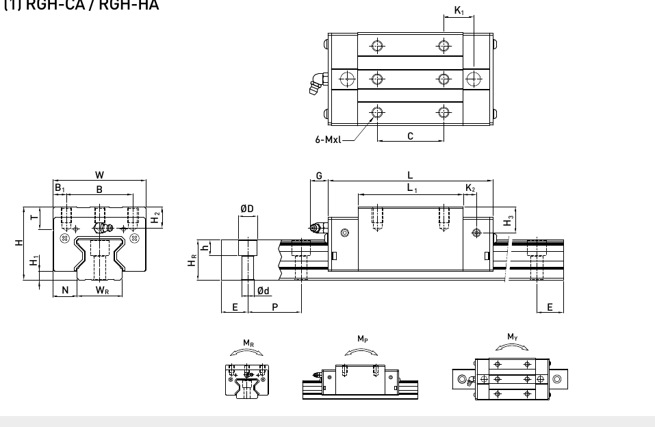
RGH roller guide blocks · mounting, rail, load and weight data
Model
Assembly H (mm)
H₁ (mm)
N (mm)
Block W (mm)
B (mm)
B₁ (mm)
Mounting C (mm)
L₁ (mm)
Block L (mm)
K₁ (mm)
K₂ (mm)
G (mm)
Block thread M×l
T (mm)
H₂ (mm)
H₃ (mm)
Rail Wᵣ (mm)
Rail Hᵣ (mm)
Rail hole D (mm)
Rail hole h (mm)
Rail hole d (mm)
Rail pitch P (mm)
Rail end E (mm)
Rail bolt
Dynamic C (kN)
Static C₀ (kN)
Mᵣ (kN·m)
Mₚ (kN·m)
Mᵧ (kN·m)
Block (kg)
Rail (kg/m)
RGH15CA
28
4
9.5
34
26
4
26
45
68
13.4
4.7
5.3
M4x8
6
7.6
10.1
15
16.5
7.5
5.7
4.5
30
20
M4x16
11.3
24
0.311
0.173
0.173
0.20
1.8
RGH20CA
34
5
12
44
32
6
36
57.5
86
15.8
6
5.3
M5x8
8
8.3
8.3
20
21
9.5
8.5
6
30
20
M5x20
21.3
46.7
0.647
0.46
0.46
0.40
2.76
RGH20HA
34
5
12
44
32
6
50
77.5
106
18.8
6
5.3
M5x8
8
8.3
8.3
20
21
9.5
8.5
6
30
20
M5x20
26.9
63
0.872
0.837
0.837
0.53
2.76
RGH25CA
40
5.5
12.5
48
35
6.5
35
64.5
97.9
20.75
7.25
12
M6x8
9.5
10.2
10
23
23.6
11
9
7
30
20
M6x20
27.7
57.1
0.758
0.605
0.605
0.61
3.08
RGH25HA
40
5.5
12.5
48
35
6.5
50
81
114.4
21.5
7.25
12
M6x8
9.5
10.2
10
23
23.6
11
9
7
30
20
M6x20
33.9
73.4
0.975
0.991
0.991
0.75
3.08
RGH30CA
45
6
16
60
40
10
40
71
109.8
23.5
8
12
M8x10
9.5
9.5
10.3
28
28
14
12
9
40
20
M8x25
39.1
82.1
1.445
1.06
1.06
0.90
4.41
RGH30HA
45
6
16
60
40
10
60
93
131.8
24.5
8
12
M8x10
9.5
9.5
10.3
28
28
14
12
9
40
20
M8x25
48.1
105
1.846
1.712
1.712
1.16
4.41
RGH35CA
55
6.5
18
70
50
10
50
79
124
22.5
10
12
M8x12
12
16
19.6
34
30.2
14
12
9
40
20
M8x25
57.9
105.2
2.17
1.44
1.44
1.57
6.06
RGH35HA
55
6.5
18
70
50
10
72
106.5
151.5
25.25
10
12
M8x12
12
16
19.6
34
30.2
14
12
9
40
20
M8x25
73.1
142
2.93
2.6
2.6
2.06
6.06
RGH45CA
70
8
20.5
86
60
13
60
106
153.2
31
10
12.9
M10x17
16
20
24
45
38
20
17
14
52.5
22.5
M12x35
92.6
178.8
4.52
3.05
3.05
3.18
9.97
RGH45HA
70
8
20.5
86
60
13
80
139.8
187
37.9
10
12.9
M10x17
16
20
24
45
38
20
17
14
52.5
22.5
M12x35
116
230.9
6.33
5.47
5.47
4.13
9.97
RGH55CA
80
10
23.5
100
75
12.5
75
125.5
183.7
37.75
12.5
12.9
M12x18
17.5
22
27.5
53
44
23
20
16
60
30
M14x45
130.5
252
8.01
5.4
5.4
4.89
13.98
RGH55HA
80
10
23.5
100
75
12.5
95
173.8
232
51.9
12.5
12.9
M12x18
17.5
22
27.5
53
44
23
20
16
60
30
M14x45
167.8
348
11.15
10.25
10.25
6.68
13.98
RGH65CA
90
12
31.5
126
76
25
70
160
232
60.8
15.8
12.9
M16x20
25
15
15
63
53
26
22
18
75
35
M16x50
213
411.6
16.20
11.59
11.59
8.89
20.22
RGH65HA
90
12
31.5
126
76
25
120
223
295
67.3
15.8
12.9
M16x20
25
15
15
63
53
26
22
18
75
35
M16x50
275.3
572.7
22.55
22.17
22.17
12.13
20.22
H = assembled height · W/L = block width/length · Wᵣ = rail width · P = rail-hole pitch. Dynamic and static ratings are in kN; rated moments are in kN·m. Block and rail weights are in kg and kg/m. RG dynamic ratings use C100R; C50R = 1.23 × C100R.
Ball screws3 families
HIWIN
Fixed-end ball screw supports
BK · Hold and locate one end of a ball screw.9 models / configurationsView specs +
BK10–BK40 fixed-end support units
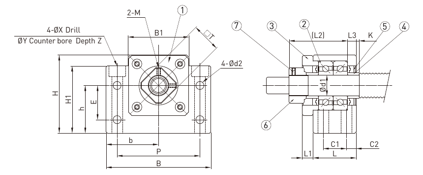
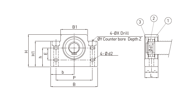
Nine published BK models. d₁ is the shaft journal, L the housing length, B the width, H the overall height, h the shaft centre height, P the mounting pitch and X the mounting-hole diameter. Dimensions are in mm; mass is in kg.
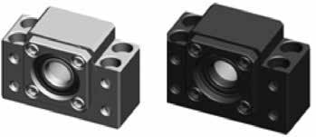
HIWIN BK support unitDimension drawing · open to enlarge
HIWIN BK standard support-unit dimensions
Model
Journal d₁
L
B
H
Centre h
Pitch P
Hole X
Mass kg
BK10
10
25
60
39
22
46
6.6
0.4
BK12
12
25
60
43
25
46
6.6
0.45
BK15
15
27
70
48
28
54
6.6
0.6
BK17
17
35
86
64
39
68
9
1.3
BK20
20
35
88
60
34
70
9
1.3
BK25
25
42
106
80
48
85
11
2.4
BK30
30
45
128
89
51
102
14
3.4
BK35
35
50
140
96
52
114
14
4.4
BK40
40
61
160
110
60
130
18
6.8
HIWIN
Supported-end ball screw units
BF · Support the opposite end of a ball screw.9 models / configurationsView specs +
BF10–BF40 supported-end units
Nine published BF models. d₁ is the shaft journal, L the housing length, B the width, H the overall height, h the shaft centre height, P the mounting pitch and X the mounting-hole diameter. Dimensions are in mm; mass is in kg.
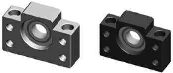
HIWIN BF support unitDimension drawing · open to enlarge
HIWIN BF standard support-unit dimensions
Model
Journal d₁
L
B
H
Centre h
Pitch P
Hole X
Mass kg
BF10
8
20
60
39
22
46
6.6
0.3
BF12
10
20
60
43
25
46
6.6
0.35
BF15
15
20
70
48
28
54
6.6
0.4
BF17
17
23
86
64
39
68
9
0.75
BF20
20
26
88
60
34
70
9
0.77
BF25
25
30
106
80
48
85
11
1.45
BF30
30
32
128
89
51
102
14
1.95
BF35
35
32
140
96
52
114
14
2.25
BF40
40
37
160
110
60
130
18
3.3
HIWIN
Flanged ball screw nuts
FSCDIN / FSIDIN · Nut geometry for matching a screw and machine axis.31 models / configurationsView specs +
FSCDIN / FSIDIN model dimensions
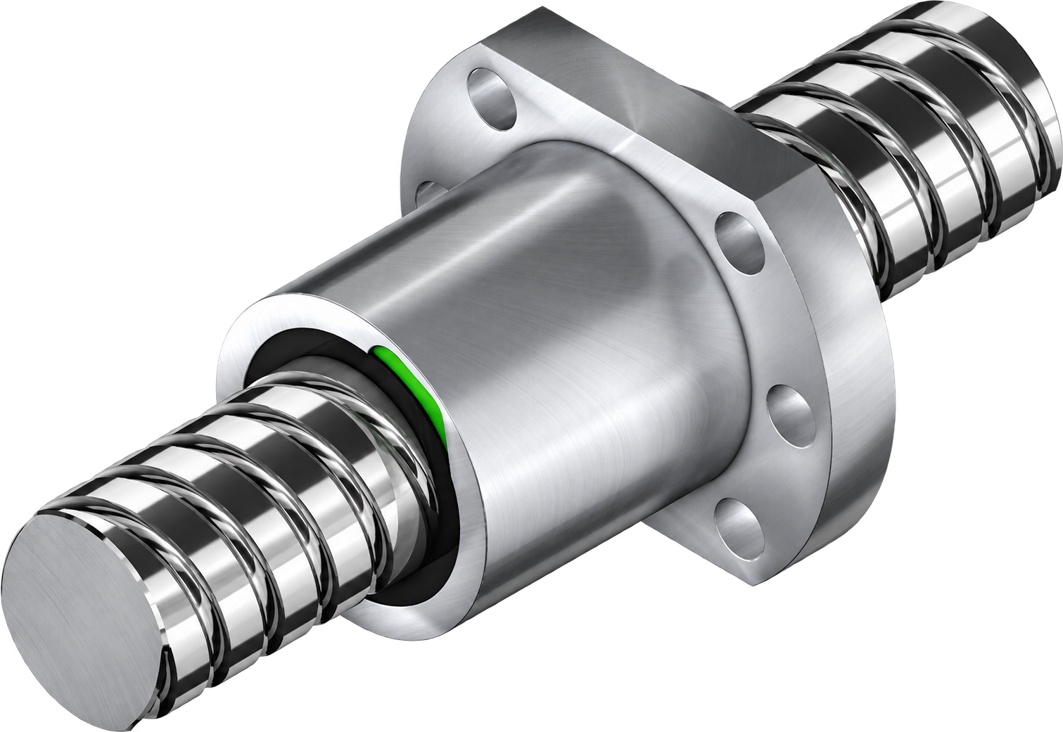
Compare 31 HIWIN flanged-nut models, including single- and double-nut variants. P is lead, ds is screw root diameter, D and D1 are nut and flange diameters, and L is nut length. Match the nut to your screw, end machining and axis drawing.
Product illustration · exact nut and shaft may vary by model.
HIWIN FSCDIN / FSIDIN flanged nut family · dimensions in mm, dynamic rating in kN
Model
Nominal screw Ø
Lead P
Shaft root Ø ds
Nut body D
Flange D1
Nut length L
Dynamic C
Max axial play
R12-05K4-FSCDIN
12
5
11.7
24
40
33
6.90
0.02
R12-10K3-FSCDIN
12
10
11.8
24
40
43
6.40
0.02
R15-05K4-FSCDIN
15
5
13.9
28
48
38
12.60
0.04
R16-05T3-FSIDIN
16
5
15.5
28
48
40
8.10
0.04
R16-10K3-FSCDIN
16
10
14.7
28
48
45
9.90
0.04
R16-16K3-FSCDIN
16
16
15
28
48
61
9.90
0.04
R16-20K2-FSCDIN
16
20
14
28
48
56
6.50
0.04
R20-05K4-FSCDIN
20
5
19.6
36
58
40
16.40
0.04
R20-10K3-FSCDIN
20
10
19.3
36
58
48
12.10
0.04
R20-20K2-FSCDIN
20
20
19.7
36
58
57
8.40
0.04
R20-20K4-DFSCDIN
20
20
19.7
36
58
57
15.30
0.04
R25-05K4-FSCDIN
25
5
24.9
40
62
43
18.20
0.04
R25-10K4-FSCDIN
25
10
24.5
40
62
61
18.10
0.04
R25-25K2-FSCDIN
25
25
24.7
40
62
70
9.30
0.04
R25-25K4-DFSCDIN
25
25
24.7
40
62
70
16.90
0.04
R32-05K6-FSCDIN
32
5
31.7
50
80
48
29.20
0.04
R32-10K5-FSCDIN
32
10
31.8
50
80
77
33.00
0.04
R32-20K3-FSCDIN
32
20
31.8
50
80
88
20.90
0.04
R32-32K2-FSCDIN
32
32
31.9
50
80
88
14.20
0.04
R32-32K4-DFSCDIN
32
32
31.9
50
80
88
25.70
0.04
R40-05K6-FSCDIN
40
5
39.4
63
93
50
31.70
0.04
R40-10K4-FSCDIN
40
10
37.8
63
93
70
55.70
0.04
R40-20K3-FSCDIN
40
20
37.9
63
93
88
42.20
0.07
R40-40K2-FSCDIN
40
40
37.9
63
93
102
28.50
0.07
R40-40K4-DFSCDIN
40
40
37.9
63
93
102
51.70
0.07
R50-05K6-FSCDIN
50
5
49.4
75
110
50
34.60
0.07
R50-10K6-FSCDIN
50
10
48
75
110
90
89.80
0.07
R50-20K5-FSCDIN
50
20
47.9
75
110
132
75.70
0.07
R50-40K3-FSCDIN
50
40
50
75
110
149
48.30
0.07
R50-40K6-DFSCDIN
50
40
50
75
110
149
87.80
0.07
R63-10T6-FSIDIN
63
10
63.1
90
125
120
75.90
0.07
Machine control1 family
HIWIN
Multi-axis motion controllers
HIWIN HIMC motion control for synchronised machine axes.1 models / configurationsView specs +
Multi-axis motion controllers
HIWIN HIMC motion control for synchronised machine axes.
Manufacturer-published controller models and axis capabilities
Model
Family
Application
Axis capability
HIMC
HIMC
Multi-axis motion control
Up to 16 synchronized
Lubrication1 family
HIWIN
Guideway and ball screw grease
Choose lubrication for the motion components in your machine.7 models / configurationsView specs +
G01–G07 grease selection
Seven published HIWIN grease formulations, each with a different operating envelope. The temperatures and viscosities below are manufacturer data; check component and grease compatibility before relubrication.
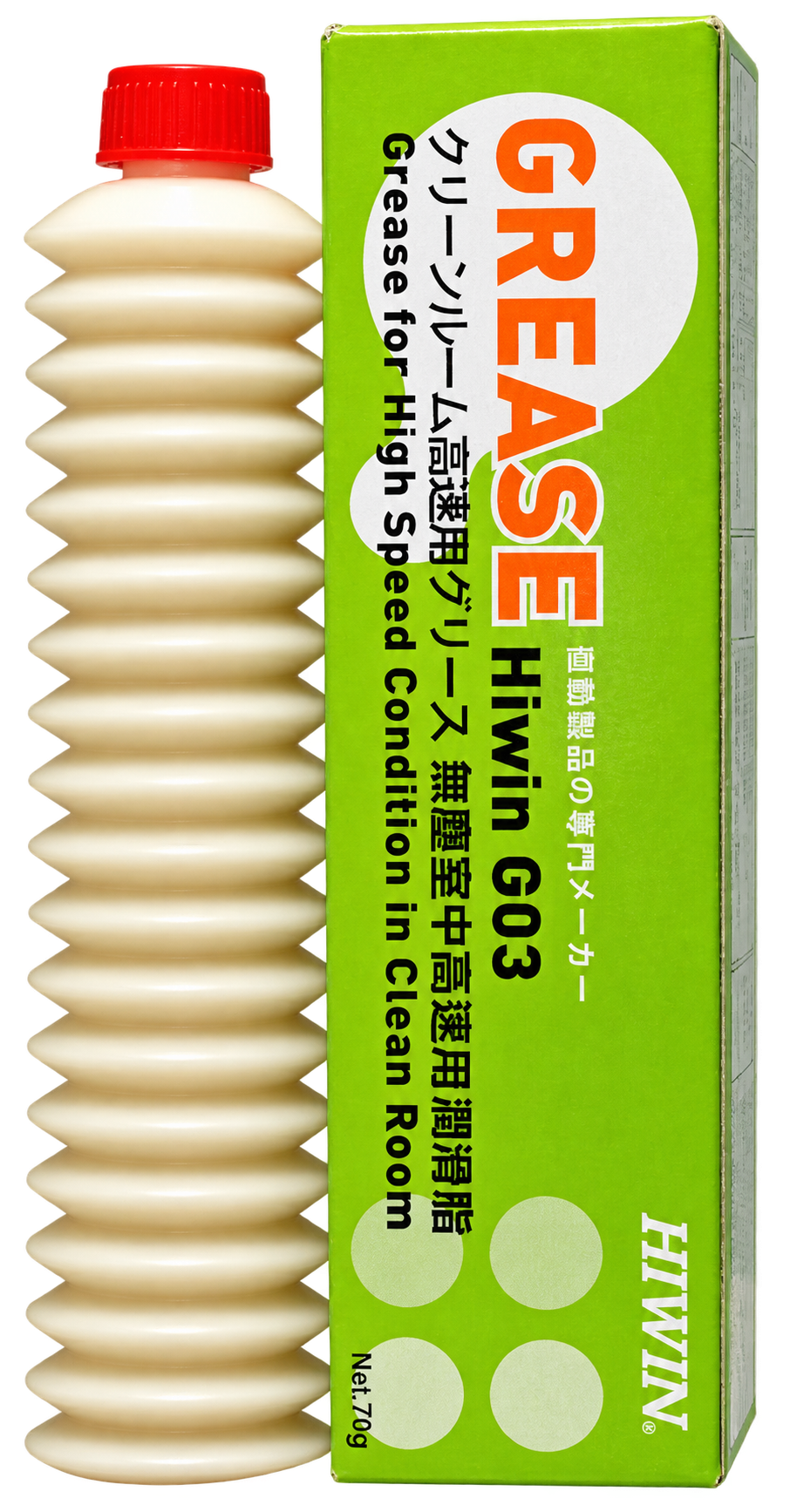
G03 product illustration · the table also covers G01, G02 and G04–G07.
HIWIN grease properties · viscosity measured at 40 °C
Series
Intended use
Base oil
Thickener
Service temperature
Viscosity, cSt
G01
Heavy load
Mineral
Polyurea
−15 to 115 °C
500
G02
Low particle emission
Synthetic hydrocarbon
Calcium soap
−30 to 140 °C
100
G03
Low particle, high speed
Synthetic hydrocarbon
Calcium soap
−45 to 125 °C
30
G04
High speed
Ester / PAO
Lithium soap
−35 to 120 °C
25
G05
General purpose
Mineral
Lithium soap
−15 to 120 °C
200
G06
High frequency / short stroke
PAO
Special lithium soap
−45 to 130 °C
32
G07
Low temperature
Mineral
Lithium-calcium soap
−50 to 80 °C
14
Sourcing & quotations
HIWIN linear guides & ball screws in Delhi
Sardar Mill Store handles enquiries for HIWIN guideways, rail blocks, ball screw nuts, end supports and lubrication from 43 Main GB Road, Delhi 110006, serving buyers in Delhi NCR and across India.
What should I send for a HIWIN quote?
Share the full guide-block code, rail length, preload or ball screw diameter and lead, plus your delivery city. Our team can match the enquiry to the relevant product family and prepare a competitive quotation.
Can I order a replacement without its full code?
Send clear photos of the marking and mounting points, measurements and machine details. Use the HIWIN tables above to identify the closest family before requesting a replacement.
 Sardar Mill Store

 HIWIN